Electret microphones are widely used in professional audio, recording, and industrial applications. Proper wiring of these microphones, whether 2-pin or 3-pin, is crucial for stable operation, optimal signal quality, and long-lasting performance. In this guide, we break down the wiring principles, polarity, and source output configurations of electret microphones, helping engineers and audio enthusiasts choose and wire their microphones correctly.
1. Internal Structure of Electret Microphones
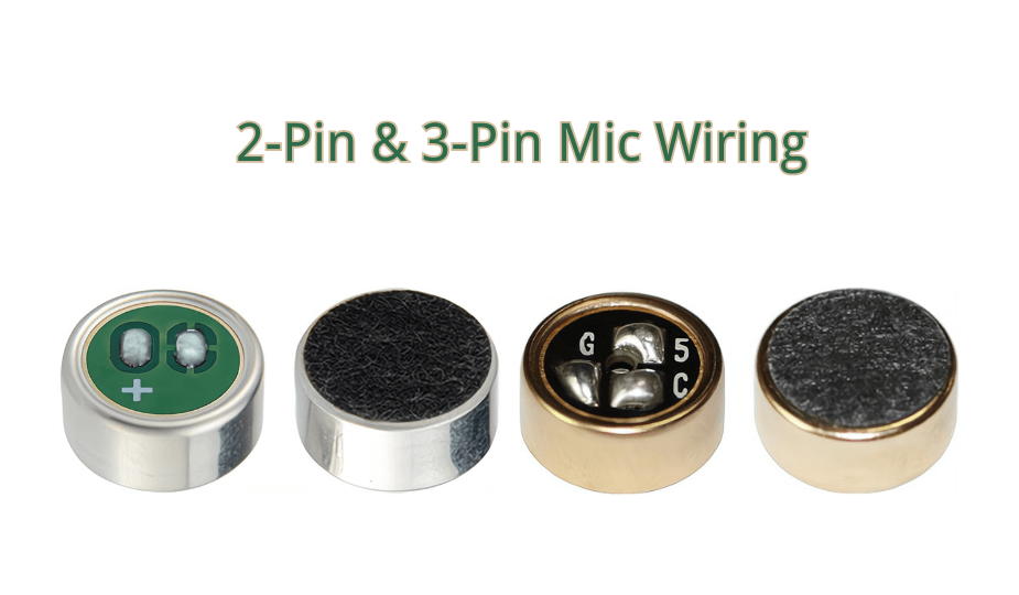
An electret microphone capsule consists of an electret diaphragm and an internal field-effect transistor (FET), either JFET or MOSFET. The FET acts as an impedance converter, allowing the weak acoustic signal generated by the diaphragm to be transmitted to external circuits with minimal loss.
Because the capsule includes an active FET, correct polarity and DC biasing are essential. Incorrect wiring may result in no output, distortion, or extremely low signal levels.
2. 2-Pin Electret Microphone Wiring
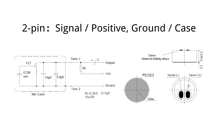
The 2-pin configuration is the simplest wiring method. In this setup, power supply and signal share the same terminal, and an external resistor provides DC bias to the internal FET. For guidance on identifying the positive and negative leads, see our Electret Microphone Polarity Guide.
Wiring Principle
- The microphone has two terminals: signal/positive and ground.
- The metal case or negative terminal is connected to ground.
- The signal terminal connects to a bias resistor (R) and the output signal node.
- The other side of the resistor connects to the positive supply voltage (Vcc).
The audio signal is extracted from the signal terminal, typically through a coupling capacitor before entering an amplifier, ADC, or recording interface.
Typical Characteristics
- Simple circuit and low component count
- Reliable for general-purpose audio or industrial use
- Moderate output impedance
3. 3-Pin Electret Microphone Wiring (Three-Terminal, Source Output)
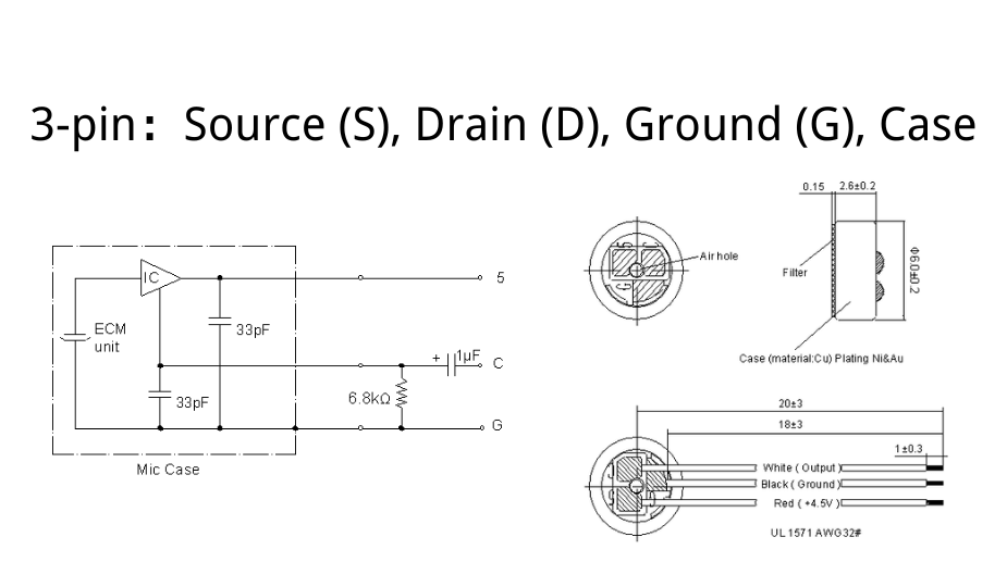
3-pin electret microphones provide separate terminals for the source, drain, and ground. This structure offers superior electrical performance, enhanced noise immunity, and better flexibility for high-end applications.
Wiring Principle
- The drain (D) is connected to the supply voltage (Vcc).
- The source (S) is connected to ground through a load resistor (internal or external).
- The audio signal is taken from the source terminal (source output).
- The microphone case or shell is connected to ground for shielding.
3-pin microphones have lower output impedance than 2-pin designs, making them suitable for longer signal traces, complex PCBs, or environments with electromagnetic interference.
Physical Identification Notes
- Three solder pads correspond to source, drain, and ground terminals.
- The metal case always connects to ground for optimal shielding.
- Source and drain pads must be identified using the datasheet or measurement; pad size may provide a hint but is not guaranteed.
4. 2-Pin vs 3-Pin: Key Differences
| Item | 2-Pin | 3-Pin |
|---|---|---|
| Wiring complexity | Simple | Moderate |
| Output impedance | Moderate | Lower, better for sensitive systems |
| Noise immunity | Standard | High, due to separate terminals and shielding |
| Design flexibility | Limited | High, suitable for professional audio setups |
| Typical applications | General industrial and simple audio | Professional audio, live streaming, broadcast, high-fidelity recording |
3-pin electret microphones excel in high-fidelity applications due to their superior electrical characteristics, physical shielding, and ability to maintain signal integrity in demanding environments.
5. Practical Selection Guidelines
- Use a 2-pin microphone for general-purpose audio and simple systems.
- Use a 3-pin microphone when low impedance, high fidelity, and strong noise immunity are required.
- Always consult the manufacturer’s datasheet for pin identification and bias requirements.
- Ensure proper grounding of the microphone case to maximize shielding.
For professional applications, such as live streaming, conference systems, and high-end recording, 3-pin microphones provide the best combination of electrical performance and physical robustness.
Conclusion
Understanding the wiring and functional differences between 2-pin and 3-pin electret microphones helps engineers and audio professionals select the right microphone for their application. Proper wiring ensures high-fidelity audio, stable operation, and excellent interference rejection. For professional-grade systems, 3-pin electret microphones with separate source, drain, and ground terminals are recommended. Explore our high-quality electret microphone selection to find the perfect microphone for your project.